On-Board Memory Interface
In this topic:
AMBA® AXI4 channel architecture
Master interface global signals
Master write address channel interface signals
Master write data channel interface signals
Master write response channel interface signals
Master read address channel interface signals
The on-board memory interface gives access to the memory resources available on the Euresys frame grabbers. It is based on AMBA® AXI4, an industry-standard protocol described in the AMBA® AXI and ACE Protocol Specification.

The on-board memory has 2 partitions: the CustomLogic partition and the FIFO Buffer partition.
FIFO Buffer partition
This part of the on-board memory resources is dedicated to the frame grabber for the temporary storage of image data.
CustomLogic partition
This part of the on-board memory resources is dedicated to CustomLogic.
The following parameters provide the base address and the size of the CustomLogic partition:
| Signal | Width | Direction | Description |
|---|---|---|---|
| onboard_mem_base | 32 | Input |
Indicates the base address of the CustomLogic partition in the On-Board Memory |
| onboard_mem_size | 32 | Input |
Indicates the size in bytes of the CustomLogic partition in the On-Board Memory |
The partitions sizes are product-specific:
| Product | Memory partition size [Gigabytes] | |
|---|---|---|
| CustomLogic | FIFO Buffer | |
| 3602 Coaxlink Octo | 1 GB | 1 GB |
| 3603 Coaxlink Quad CXP-12 | 1 GB | 1 GB |
| 3603-4 Coaxlink Quad CXP-12 | 2 GB | 2 GB |
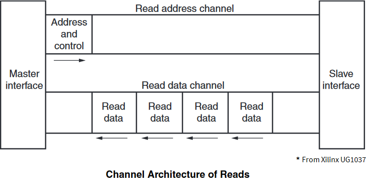
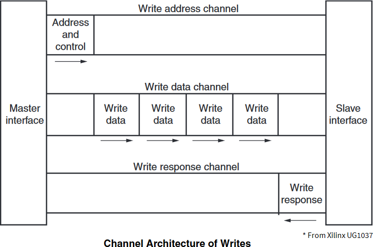
AMBA® AXI4 channel architecture
AMBA® AXI4 is a memory-mapped interface that consists of five channels:
| □ | Write Address Channel |
| □ | Write Data Channel |
| □ | Write Response Channel |
| □ | Read Address Channel |
| □ | Read Data Channel |
Data can move in both directions between the master and slave simultaneously, and data transfer sizes can vary. The limit in AMBA® AXI4 is a burst transaction of up to 256 data transfers.
The following sections briefly describe the AMBA® AXI4 signals.
For a complete view of signal, interface requirements and transaction attributes, please refer to AMBA® AXI and ACE Protocol Specification document at www.amba.com.
Master interface global signals
| Signal | Width | Direction | Description |
|---|---|---|---|
|
m_axi_resetn |
1 | Input |
RESETn resets the AMBA® AXI4 interface. |
Master write address channel interface signals
| Signal | Width | Direction | Description | ||||||||||||
|---|---|---|---|---|---|---|---|---|---|---|---|---|---|---|---|
|
m_axi_awaddr |
32 |
Output |
Write address. The write address gives the address of the first transfer in a write burst transaction. |
||||||||||||
|
m_axi_awlen |
8 |
Output |
Burst length. The burst length gives the exact number of transfers in a burst. This information determines the number of data transfers associated with the address. Burst_Length = AWLEN[7:0] + 1 |
||||||||||||
|
m_axi_awsize |
3 |
Output |
Burst size. This signal indicates the size in bytes of each transfer in the burst. Burst_Size = 2^AWSIZE[2:0] |
||||||||||||
|
m_axi_awburst |
2 |
Output |
Burst type. The burst type and the size information, determine how the address for each transfer within the burst is calculated. Burst_Type: "00" = FIXED; "01" = INCR; "10" = WRAP |
||||||||||||
|
m_axi_awlock |
1 |
Output |
Lock type. Provides additional information about the atomic characteristics of the transfer. Atomic_Access: '0' Normal; '1' Exclusive |
||||||||||||
|
m_axi_awcache |
4 |
Output |
Memory type. This signal indicates how transactions are required to progress through a system. Memory_Attributes:
|
||||||||||||
|
m_axi_awprot |
3 |
Output |
Protection type. This signal indicates the privilege and security level of the transaction, and whether the transaction is a data access or an instruction access. Access_Permissions:
|
||||||||||||
|
m_axi_awqos |
4 |
Output |
Quality of Service, QoS. The QoS identifier sent for each write transaction. Quality_of_Service: Priority level |
||||||||||||
|
m_axi_awvalid |
1 |
Output |
Write address valid. This signal indicates that the channel is signaling valid write address and control information. |
||||||||||||
|
m_axi_awready |
1 |
Input |
Write address ready. This signal indicates that the slave is ready to accept an address and associated control signals. |
It is strongly recommended to set m_axi_awqos values below 8 to not disturb the other agents connected to the On-Board Memory.
The descriptions are excerpts from AMBA® AXI and ACE Protocol Specification.
Master write data channel interface signals
| Signal | Width | Direction | Description |
|---|---|---|---|
|
m_axi_wdata |
W |
Output |
Write data. |
|
m_axi_wstrb |
W/8 |
Output |
Write strobes. This signal indicates which byte lanes hold valid data. There is one write strobe bit for each eight bits of the write data bus. |
|
m_axi_wlast |
1 |
Output |
Write last. This signal indicates the last transfer in a write burst. |
|
m_axi_wvalid |
1 |
Output |
Write valid. This signal indicates that valid write data and strobes are available. |
|
m_axi_wready |
1 |
Input |
Write ready. This signal indicates that the slave can accept the write data. |
In the Width column: "W" refers to MEMORY_DATA_WIDTH, the data width of the write data channel.
| ● | 3602 Coaxlink Octo |
| □ | (1-camera, custom-logic) => W = 128 ; |
| □ | (2-camera, line-scan, custom-logic) => W = 256; |
| ● | 3603 Coaxlink Quad CXP-12 and 3603-4 Coaxlink Quad CXP-12 |
| □ | (1-camera, custom-logic) => W = 256; |
| □ | (1-camera, line-scan, custom-logic) => W=256; |
| □ | (2-camera, custom-logic) => W = 256; |
| □ | (4-camera, custom-logic) => W = 256; |
The descriptions are excerpts from AMBA® AXI and ACE Protocol Specification.
Master write response channel interface signals
| Signal | Width | Direction | Description | ||||||||||||
|---|---|---|---|---|---|---|---|---|---|---|---|---|---|---|---|
|
m_axi_bresp |
2 |
Input |
Write response. This signal indicates the status of the write transaction. Response:
|
||||||||||||
|
m_axi_bvalid |
1 |
Input |
Write response valid. This signal indicates that the channel is signaling a valid write response. |
||||||||||||
|
m_axi_bready |
1 |
Output |
Response ready. This signal indicates that the master can accept a write response. |
The descriptions are excerpts from AMBA® AXI and ACE Protocol Specification.
For m_axi_bresp:
| □ | OKAY: Normal access success. Indicates that a normal access has been successful. Can also indicate an exclusive access has failed. See OKAY, normal access success. |
| □ | EXOKAY: Exclusive access okay. Indicates that either the read or write portion of an exclusive access has been successful. |
| □ | SLVERR: Slave error. Used when the access has reached the slave successfully, but the slave wishes to return an error condition to the originating master. |
| □ | DECERR: Decode error. Generated, typically by an interconnect component, to indicate that there is no slave at the transaction address. |
Master read address channel interface signals
| Signal | Width | Direction | Description | ||||||||||||
|---|---|---|---|---|---|---|---|---|---|---|---|---|---|---|---|
|
m_axi_araddr |
32 |
Output |
Read address. The read address gives the address of the first transfer in a read burst transaction. |
||||||||||||
|
m_axi_arlen |
8 |
Output |
Burst length. The burst length gives the exact number of transfers in a burst. This information determines the number of data transfers associated with the address. Burst_Length = ARLEN[7:0] + 1 |
||||||||||||
|
m_axi_arsize |
3 |
Output |
Burst size. This signal indicates the size in bytes of each transfer in the burst. Burst_Size = 2^ARSIZE[2:0] |
||||||||||||
|
m_axi_arburst |
2 |
Output |
Burst type. The burst type and the size information, determine how the address for each transfer within the burst is calculated. Burst_Type: "00" = FIXED; "01" = INCR; "10" = WRAP |
||||||||||||
|
m_axi_arlock |
1 |
Output |
Lock type. Provides additional information about the atomic characteristics of the transfer. Atomic_Access: '0' Normal; '1' Exclusive |
||||||||||||
|
m_axi_arcache |
4 |
Output |
Memory type. This signal indicates how transactions are required to progress through a system. Memory_Attributes:
|
||||||||||||
|
m_axi_arprot |
3 |
Output |
Protection type. This signal indicates the privilege and security level of the transaction, and whether the transaction is a data access or an instruction access. Access_Permissions:
|
||||||||||||
|
m_axi_arqos |
4 |
Output |
Quality of Service, QoS. The QoS identifier sent for each write transaction. Quality_of_Service: Priority level |
||||||||||||
|
m_axi_arvalid |
1 |
Output |
Read address valid. This signal indicates that the channel is signaling valid read address and control information. |
||||||||||||
|
m_axi_arready |
1 |
Input |
Read address ready. This signal indicates that the slave is ready to accept an address and associated control signals. |
It is strongly recommended to set m_axi_awqos values below 8 to not disturb the other agents connected to the On-Board Memory.
The descriptions are excerpts from AMBA® AXI and ACE Protocol Specification.
Master read data channel interface signals
| Signal | Width | Direction | Description |
|---|---|---|---|
|
m_axi_rdata |
W |
Input |
Read data. |
|
m_axi_rresp |
2 |
Input |
Read response. This signal indicates the status of the read transfer. Response: "00" = OKAY; "01" = EXOKAY; "10" = SLVERR; “11” = DECERR |
|
m_axi_rlast |
1 |
Input |
Read last. This signal indicates the last transfer in a read burst. |
|
m_axi_rvalid |
1 |
Input |
Read valid. This signal indicates that the channel is signaling the required read data. |
|
m_axi_rready |
1 |
Output |
Read ready. This signal indicates that the master can accept the read data and response information. |
In the Width column: "W" refers to MEMORY_DATA_WIDTH, the data width of the write data channel.
| ● | 3602 Coaxlink Octo |
| □ | (1-camera, custom-logic) => W = 128 ; |
| □ | (2-camera, line-scan, custom-logic) => W = 256; |
| ● | 3603 Coaxlink Quad CXP-12 and 3603-4 Coaxlink Quad CXP-12 |
| □ | (1-camera, custom-logic) => W = 256; |
| □ | (1-camera, line-scan, custom-logic) => W=256; |
| □ | (2-camera, custom-logic) => W = 256; |
| □ | (4-camera, custom-logic) => W = 256; |
The descriptions are excerpts from AMBA® AXI and ACE Protocol Specification.
